
A Detailed Explanation of the Types, Structure and Working Principles of Check Valves
author: ATHENA GROUP
2026-05-25

1.Introduction to Check Valves
A check valve, also known as a non-return valve, is a type of automatic valve that relies on the pressure of the medium flowing within the pipeline to move the valve disc, allowing the valve to open and close. When the medium stops flowing, the check valve disc closes, effectively preventing backflow in the pipeline, which plays a significant role in ensuring the safety of the pipeline.
Check valves have a long history, dating back to ancient civilizations around 2000 BCE, initially used in irrigation and salt wells with bamboo and wooden plate structures. With the advancement of European metallurgical technology and the invention of the steam engine in the 18th century, check valves entered the era of metal manufacturing and were widely applied in industry. Through the Industrial Revolution of the 19th century and the development of composite material technology in the 20th century, modern check valves have evolved into key fluid control components that operate automatically based on fluid flow, with a wide variety of types.
The check valve gets its name from its core function — preventing backflow of the medium. It opens automatically according to the pressure difference when the medium flows forward, and closes automatically due to its own weight, spring force, or reverse pressure when the flow reverses or stops, blocking backflow. Therefore, it is called a 'check valve' and is also commonly referred to as a one-way valve or non-return valve.
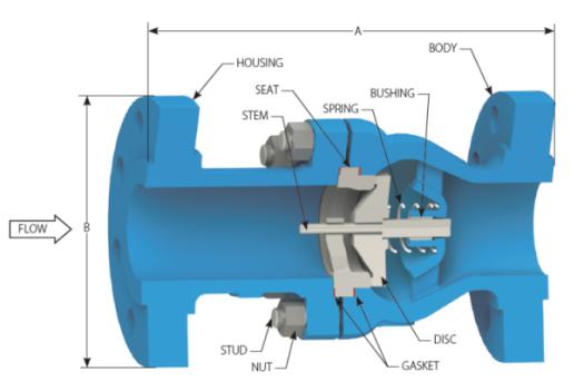
The core structure of a standard check valve typically includes the following main components:
Body: The main housing, connected to the pipeline and housing internal components, serves as the pressure-bearing foundation, commonly made of cast steel, stainless steel, cast iron, etc.
Seat: The sealing surface that fits closely with the valve disc, crucial for achieving leak-proof sealing.
Disc: The core moving component, opens with flow and closes against flow, determining the sealing performance and opening/closing type.
Connecting Components:
Lift Type: Guide bracket, restricts the linear movement of the valve disc;
Swing Type: Pin shaft, supports the rotary opening and closing of the valve disc.
Bonnet / Gasket: The valve cover encloses the interior of the valve body, and the gasket ensures a sealed connection, preventing medium leakage.
2.Lift check valve
The disc of a lift check valve operates automatically. Typically, a conical disc is pressed against a metal seat between the inlet and outlet of the valve. A spring can be added to the disc for preload. When fluid flows in the forward direction, the conical disc lifts off the seat under fluid pressure, opening the valve. During backflow, the disc returns to the seat under the combined action of its own weight, the spring force, and the backflow pressure, closing the valve.

The main advantage of the lift check valve is its simple structure. Since the conical valve disc is the only moving part, the valve is sturdy and durable, requires almost no maintenance, and experiences minimal wear due to the metal valve seat. The limitation of the lift check valve is that it must be installed in a horizontal pipeline. The valve disc of a lift check valve can move freely up and down, and the fluid should push the valve disc from below. When the pressure at the lower inlet of the valve disc is less than the pressure at the upper outlet, the valve disc closes automatically under the combined action of its own weight and the pressure of the fluid above.
Compared with other types of check valves, the lift check valve has a short stroke, so it only requires a relatively short stroke to fully open the valve.
Compared with other types of check valves, the lift check valve has a short stroke, so it only requires a relatively short stroke to fully open the valve.
2.1 Straight-through lift check valve
The straight-through lift check valve is a type of one-way valve that relies on the pressure of the medium itself to automatically open and close the valve disc, preventing backflow in the pipeline. Its appearance is similar to that of a globe valve, and the valve disc moves vertically along the centerline of the valve body. This valve has a compact structure and good sealing performance and is usually only suitable for horizontal installation in pipelines. It is suitable for mediums such as water, steam, and oil, and is often used in high-pressure, small-diameter scenarios in industrial pipelines.

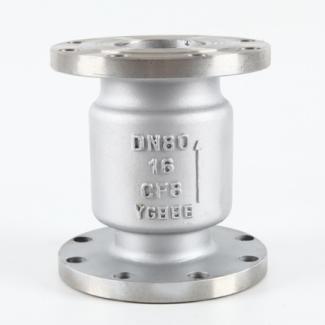
2.2 Vertical lift check valve
The vertical lift check valve is a type of check valve that relies on the flow of the medium itself to automatically open and close the valve disc, preventing backflow in the pipeline. It is specifically designed for vertical pipelines, with fluid flowing from bottom to top, and the valve disc sliding along the vertical centerline of the valve body. It has the advantages of a simple structure, good sealing performance, and is suitable for clean water or similar media.
3.Swing check valve
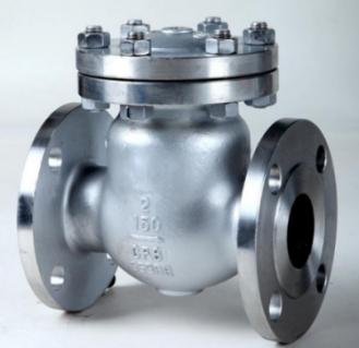
A swing check valve is a check valve in which the valve disc rotates around a rocker shaft inside the valve body. The operating principle of a swing check valve is that when the fluid flow rate and pressure exceed the set valve opening pressure, the valve disc automatically rotates in the opening direction, allowing normal fluid flow; when the fluid flow rate and pressure fall below the closing pressure or the fluid flows in the reverse direction, the valve disc closes, ensuring unidirectional flow of the fluid.
The swing check valve is mainly composed of four parts: the valve body, valve cover, valve disc, and rocker arm. It controls the swing flow within the pipeline through the internal valve disc and rocker shaft. The passages inside the valve are streamlined, which can create resistance to control the flow of the medium. The swing check valve uses a spherical connection structure to allow the valve disc a certain degree of freedom, resulting in a longer service life.
In addition, swing check valves are usually equipped with auxiliary springs and a weighted structure to improve the sealing of the pipeline, ensuring good sealing performance even under low-pressure conditions. At the same time, a damping structure is also installed on the valve disc to prevent water hammer caused by the sudden closure of the valve disc when the medium flows through the pipeline, thereby reducing wear on the valve seat.

3.1 Single-disc swing check valve
The single-disc swing check valve is a type of one-way valve that opens and closes automatically based on the backflow pressure of the medium and the weight of the disc. It features a simple structure, low flow resistance, and good sealing performance. Its single-disc design effectively prevents backflow in the pipeline, protecting pumps and pipelines from water hammer damage.

3.2 Double-disc swing check valve
The double-disc swing check valve is an automatic anti-backflow valve with a wafer-type connection, which swings open and closed around a pin by two semicircular valve discs loaded with springs. It has a compact structure, small size, light weight, and features good sealing performance and quick water shut-off.
4.Butterfly check valve
The butterfly check valve has a wafer-type connection, and the valve disc consists of two semicircular butterfly plates connected by a valve stem, with a spring for forced reset. The working principle of the butterfly check valve is: when the medium flows through the valve body passage, the medium pressure exceeds the spring force, pushing the two butterfly plates open, allowing the medium to flow; when the medium stops flowing, the two butterfly plates are forced to reset by the spring force, closing the valve and preventing backflow. Butterfly check valve diagram. The butterfly check valve, also known as a double-wing check valve, can have a sealing surface made of wear-resistant material overlaid on the body or rubber lining, offering a wide range of applications and reliable sealing. The butterfly check valve is an automatic valve and does not require manual operation.
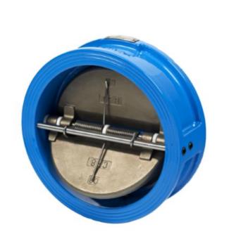
Compared with other check valves, it is smaller in size and lighter in weight, making installation, removal, and maintenance in pipelines more convenient. The two valve discs close quickly, producing low water hammer pressure; the opening and closing stroke is short, which has little impact on the valve discs. The flow passage is generally smooth, resulting in low fluid resistance, sensitive valve disc operation, and good sealing performance. The structure of the butterfly check valve is simple and compact, aesthetically pleasing, and made using special casting and painting processes, giving it a long service life and good stability.
5.Ball check valve
The ball check valve, also known as a non-return valve or backflow preventer, is a type of check valve that uses a multi-ball, multi-channel, and multi-conical backflow structure. When the water pump starts, water pressure pushes the rubber ball to the right-side cone to open it; when the pump stops, the backflow pressure resets the rubber ball to close it. The multi-channel design allows the liquid to flow through independent passages, and the shaftless structure reduces mechanical friction, featuring low flow resistance, significant shock absorption, and low water quality requirements. The rubber ball is a hollow steel ball coated with rubber, and with a vacuum ball picker, rapid and non-destructive retrieval can be achieved. This device consists of a specially designed suction cup, a vacuum pump, and an intelligent control valve, reducing the ball retrieval time from half an hour to 5 minutes.
6.Conclusion
With the continuous development of industrial technology, the requirements for the materials, craftsmanship, and intelligent adaptability of check valves in the field of fluid control are also constantly increasing. In the future, check valves will continue to evolve toward greater efficiency, higher durability, and better adaptability to complex working conditions, always serving as the 'safety guard' against backflow in pipeline systems and playing an irreplaceable role in various fluid transport scenarios. Moreover, having a precise understanding of the structures and principles of different types of check valves will provide important theoretical support for selection, installation, and maintenance in practical applications, helping to improve the overall operational efficiency and safety of fluid systems.
 Characteristics, Applications and Advantages of Carbon Steel Globe Valves
  Why Are Instrument Valves Indispensable for Industrial Control Systems?
  What is Bi-Directional Valves?
  How Does a Ball Type Check Valve Prevent Pipeline Medium Backflow?
  Selection and Precautions for Natural Gas Valves
  Athena Engineering S.R.L Wraps‑up OGA 2026 Kuala Lumpur
  What is a Gate Valve? What is Its Working Principle?
  T-Type / T-Pattern / Straight Pattern Globe Valve
  Knife Gate Valve vs Wedge Gate Valve: Which Is Better for Your Industrial Piping?
  Cryogenic Ball Valve Comprehensive Product Overview
  Causes and Treatments for Poor Valve Shut‑Off
  Athena Triple Offset Butterfly Valves
  What is the Difference Between Swing Check Valve and NRV? A Complete Explanation
  Common Connection Types of Valves
  5 Piping Design Mistakes That Are Killing Your Valves
  Float Valve: Structure, Principle and Application
  High Pressure Needle Valve High-Precision Fluid Control Valve
  What is a Piston Check Valve?
  Meet Us at OGA 2026 | Booth 6802, Hall 6
  What is a Level Gauge? Working Principles, Types and Industrial Applications